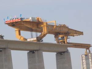
900t bridge girder launching gantry for high-speed railway
(1) Brief introduction
Scope of application and purpose
- can bridge full span box-type prestressed concrete girder for double track special railway passenger line with straight line, curve line(radius >2500m),longitudinal gradient 20‰,32m,24m,20m equal span or changing span
- erect bridge girder at the beginning and at the end
- cross one pier to another pier by automatic shifting
- two ways to shift between bridges: carried by girder transporter and automatic transfer
(2)Design and manufacturing standard
2.1 The Beijing-Shanghai high speed railway design provisional regulations railway construction letters [2003]13
2.2 The Beijing-Shanghai high speed railway equipment research technical conditions high speed railway office letter [2003]23
2.3 Standard for railway bridge and tunnel construction TB10203-2000
2.4 Railway bridge reinforced concrete and prestressed concrete structure design codes TB10002.3-98
2.5 Crane design codes GB3811-83
2.6 Crane test standard and procedure GB5905-86
2.7 Lifting machinery safety regulations GB6067-85
2.8 Girder installation regulations for railway bridge girder launcher TB/T10401.1-2003
2.9 Steel structure design codes GBJ50017-2003
2.10 General assembly technical demands JB/ZQ400.9-86
2.11 General technical demands for welding parts JB/ZQ4000.3-86
2.12 Fastener mechanical property GB3098-82
2.13 Low voltage apparatus basic standard GB1497-85
2.14 General technical conditions for hydraulic system GB/T3766-2001
2.15 Bridge crane type test rules TSG Q2002-2004
(3) Main technical parameters
3.1 Rated lifting capacity 900t
3.2 Installed girder type
32m,24m, 20m double line box girder with equal or shift span
3.3 Trolley lifting speed 0- 0.5m/min
3.4 Lifting height 7.5m
3.5 Lateral fine adjustment speed 0-0.1m/min
Lateral fine adjustment distance ±200mm
3.6 Trolley longitudinal moving speed
0-3m/min(heavy load)0-5m/min(no load)
3.7 Lifting ways: four points lifting, three point balance
3.8 Ways for installing girders: simple support installation
for one span, as installing girders, max reaction force of rear
leg single side to the abutment or girder installed ≤464.5t,
max reaction force of front leg to the abutment ≤377.8t
3.9 Crossing pier ways crossing pier and moving
forward automatically; moving speed 0-3m/min; max reaction
force of guide beam leg single point to abutment ≤106t.
Rear leg moves on the temporary rail on the bridge deck, rail
distance 5.9m, single side max reaction force to the abutment
or girder installed ≤155t, wheel pressure 77.5t
3.10 Min radius of curvature of curved bridge Rmin≥2000m
3.11 Operating mode cabin control, remote control
3.12 Applicable longitudinal gradient 20‰,
lateral gradient 4%
3.13 Applicable working temperature -20℃~50℃
3.14 Applicable wind force 6 grade (working condition)
11 grade (non-working condition)
3.15 Auxiliary trolley technical parameters and guide beam Displacement ways:
Lifting capacity: 80t
Moving distance: 19.5m
Moving speed: 0-3m/min
Guide beam displacement ways: trolley of front guide beam, auxiliary leg and auxiliary trolley work together
3.16 Work efficiency 2 span/8h (moving distance 8km)
3.17 Out dimension
Mainframe (length x width x height) 73.92×17.8×13.48m
Guide beam (length x width x height) 36.84×1.8×2.4m
Complete machine (length x width x height) 89.15×17.8×13.48 m
Out dimension as carrying girders
(length x width x height) 73.92×17.8×11.48m
Out dimensions to pass tunnels with girders
(length x width x height) 73.92×10.89×7.74m
3.18 Power 300KW, max power of single work 37×4kw
3.19 Rated power or motor 300kw
3.20 Total weight of the complete machine: 580t;
Main frame 513t, guide beam 67t.


