Upstroke Movable Support System

Pictrues

Application range and usehide/show
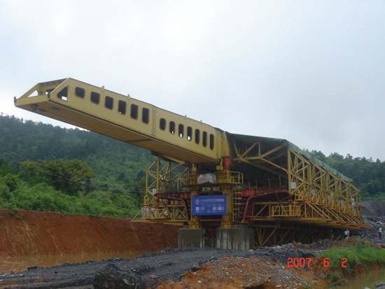
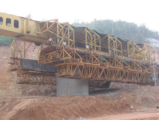
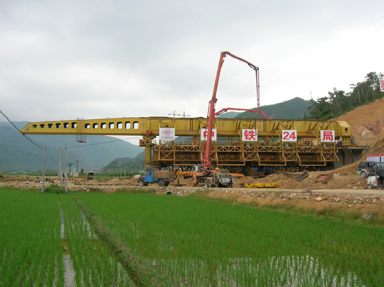
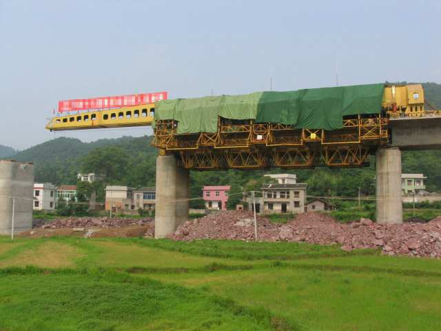
MZ Upstroke Bridge Creating Machine is the exclusive equipment for the continuous box girder field casting construction in the railway passenger transportation line project.
Main features and advantageshide/show
◆ This machine can realize the moving from one pier to next pier by itself, without other auxiliary facilities on the ground. It owns the characteristics of high mechanical degree, safety and reliability.
◆ Equip with the ceilings of rain-proof and sunscreen, the machine can operate in any time and any weather to improve the working efficiency and guarantee the construction period.
◆ While erecting the continuous girder or transferring, we just need to expand the side mould frame and base mould. There is no need to dismantle the whole machine in order to improve the transferring efficiency.
◆ We stick to the symmetrical design principles for the main girder and mould frame. So if there is the two-way construction condition, we just need to replace the position of the front guide girder, front and rear support leg, auxiliary support legs.
◆ The machine can accomplish the segmental assembly erection of 32m box girder without making the adjustment on the main girder and support leg mechanism.
Main Parametershide/show
| Item/ Data /Model | MZ900S | MZ460S |
|---|---|---|
| Girder-casting Weight(one time) (t) | 900 | 460 |
| Girder Length (m) | 32.6/24.6 | 29.94/24.96 |
| Self Weight (t) | 450 | 310 |
| Longitudinal Speed (m/min) | 0.5 | 0.5 |
| Power(kw) | 50 | 46.5 |
| Max Anti-force At Working (m/min) | 5805 | 3333 |
| Dimension(m) | 62.5×20.6×5.6 | 58.5×13.8×5 |
| Average Construction Speed (day/span) | 12 | 12 |
| Applicable Curve Radius (m) | R>2000 | R>2000 |
| Applicable Longitudinal/Transverse Gradient | 2 %/2% | 2 %/2% |
The design basis of producthide/show
MZ UPstroke Bridge Creating Machine in passenger transportation line project is designed according to the 《Purchase and Sale Agreement》, the drawing of concrete box-girder, piers and abutment provided by customers and some national design standard in the field of machinery.
《Crane Design Standard》 (GB/T3811)
《Steel Structure Design Standard》 (GB50017)
《Code for design of Railway Bridges and Culverts》 (TBJ2)
《Construction Standard of Railway Bridges and Culverts》 (TBJ203)
《The Steel Rope for Important Purpose》 (GB8918)
《Code for Construction and Acceptance of Electrical Appliance Installation Engineering》 (GB50256)
《The General Technical Conditions for Hydraulic System》 (GB 3766)
《Railway Construction Safety Regulations》 Part-I (TB19491.1)
《Mechanical Properties of Fasteners—Bolts, Screws and Studs》 (GB 3098.1)
Main requirements of designhide/show
● The machine can meet the needs of the 32m, 24m full-span box girder erection in the railway passenger double line project.
● While the machine needs to erect the continuous girder or transferring, just to expand the side mould frame and base mould.
● The machine moves with the walking hydraulic jacking system, replacing the support legs with the steel rope traction method.
● The single main girder structure with a rigid and flexible support leg as the supporting.
● The weight-casting capacity: about 900t
● Max. anti force at working: 5805KN
● Applicable curve radius: R>2000m
● Applicable longitudinal slope/ transverse slope: 2%/2%
● The deflection of main girder: 1/700
Main mechanical manufacturing technologyhide/show
quality control of manufacturing processhide/show
Tracing data and leaving factory data of producthide/show
The method and steps of installationhide/show
Checking methods after installation of producthide/show
operating requirements and attentionhide/show
Time and item of maintenancehide/show
Disassembly and steps of transferring sitehide/show