What is the structure and working principle of HZQ900t bridge girder launcher?
HZQ900t bridge girder launcher is designed according to actual working conditions such as multi-girder types for special passenger line, large lifting capacity, high construction precision and better adaptability of curved bridge and skewed bridge construction.
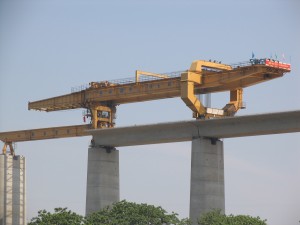
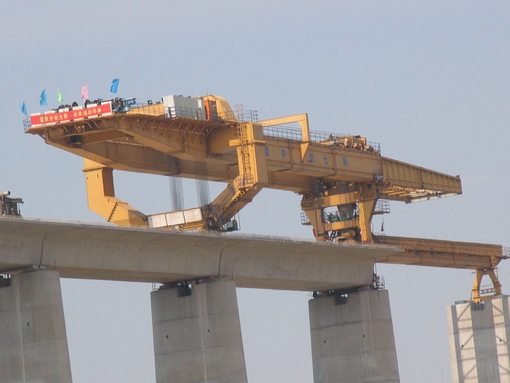
HZQ900 type bridge girder launcher is mainly made up of main girder and front, rear cross girder; front lifting trolley, rear lifting trolley, rear part winch system; front leg; rear leg and rear leg bogie; auxiliary leg and bogie; guide beam; cantilever beam and auxiliary trolley; control cabin and electrical control system; hydraulic system and power system, safety protection device and other parts
4.1 Main girder and front, rear cross girder and guide beam
4.1.1 Main girder and front, rear cross girder
Main girder (drawing 4.2) is double box girder structure, basic section length 12m, total length 55.01m, height 2.8m, width 1.5m, total weight 204t. the main girder is divided into 5 sections to be fabricated. Front and rear cross girder connect the main girder together.
Top cover plate of main girder is equipped with two moving rails for trolley longitudinal moving, rail distance 1.3m, rail material: square steel with section 100 x 100, bumper is set at the end of the rail.
Main girder is main structure to bear load directly. To keep the trolley balanced and set pre-camber scientifically, main girder simply support section camber control 55-65mm, rear cantilever section upper camber control 32mm~42mm; worst condition for the rear cantilever is that trolley lifts box concrete girder from the lifting point 6m
Guide beam is of box structure, double rails are laid on the tope part, rail distance 1.6m, box type support leg is set at the bottom part; the leg is a little higher than box concrete girder to meet the demand of installing the last girder, convenient for the guide beam to get out of the abutment.
Structure dimension (length x width x height) 36.3m×1.8m×2.4m, structure self-weight 67t, upper camber control 50-60mm.
4.2 Lifting trolley and lifting system
The bridge girder launcher is equipped with front and rear lifting trolley with independent lifting system, moving system and lateral moving system. Lifting trolley have functions of longitudinal moving, lateral moving and fine adjustment which can ensure to install the box girder correctly.
The trolley is equipped with fixed pulley group constituting lifting system with movable pulley group of the sling. Set up oil cylinder pushing and longitudinal moving device, lateral distance to the left and right ±200mm, meet the demand of fine adjustment of girder and installing girders at a curved degree
Four winches is set up at the rear part of the main girder, steel wire rope enters into guide beam trolley through guide pulley, forming lifting system with pulley block. The winch is equipped with head and end brake devices, two sets in total, rope angle is < 1.5 degree, rope suspension is natural and convenient
Max out dimension of guide beam trolley (length x width x height) 5.134×8.107×1.386m, weight 37.3t, rated lifting capacity for one lifting trolley 450t, power 74kw, power for trolley moving system 22kw
4.3 Auxiliary trolley
Auxiliary trolley is suspended at bottom part of the front cantilever to lift and move guide beam, moving depends on chain drive and frequency control of motor speed, driving motor power 1.1KW x 2, Lifting system is equipped with balanced girder. Equipped with hydraulic lateral moving device to meet the demand of crossing piers. Lifting system and lateral moving device of the auxiliary trolley share one hydraulic pump station, pump station power 5.5kw; max out dimension of auxiliary trolley 6.836m x 1.62m x 1.344m, weight 5.1t
4.4 Rear leg and moving system
Rear leg is o-type closed structure, upper part (the third section) and main girder is connected with M30 high tension bolt. Max section (the first section) bottom part is connected with moving bogie (drawing 4.5), one pair of moving driving wheel is set up respectively at the right and left, middle hinge seat cushion block at the bottom part of the gearbox provides support; set up hydraulic oil cylinder, realize change between load-carrying device (hinge seat cushion block support) and moving wheel.
Left and right moving gearbox moves on the special rail, rail distance 5900mm, rail type Q120
One hydraulic pump station is installed at the bottom part of the support leg, pump station 7.5kw.
4.5 Auxiliary support leg and moving system
Auxiliary support leg is main load-bearing and driving parts as the bridge girder launcher crosses piers, as auxiliary lifting point as moving guide beam longitudinally
Auxiliary support leg is made up of cross girder, fixed section, telescopic section, jacking oil cylinder, moving wheels and hanging wheels, it is connected with main girder of the bridge girder launcher by cross girder. Out dimension (length x width x height) 8.827m×5.415m×1.119m, weight 18t
Two jacking oil cylinders connect fixed section and telescopic section, adjust the height of the support leg. Telescopic section is connected with spherical core plate by one pin, it support on the moving trolley
As the bridge girder launcher crosses piers, bottom moving system of auxiliary support leg moves along the upper rail of guide beam, rear leg moves along temporary rail on the upper part of girders installed; auxiliary support leg and rear leg moving system works at the same time to finish crossing piers
4.6 Front leg
As front support point of main girder, the front leg uses hydraulic telescopic structure to meet the demand of bridge longitudinal slope, span shift work and last girder installation
Upper part of the front leg is equipped with shift roller, driving power of reducer and motor 1.1KW×4=4.4KW, it can move longitudinally along rail at the bottom cover plate of main girder, meet the demand of span shift.
Folding sections are set up at lower part of front support leg, spiral fine-tuning is set up at the bottom part, fold up to two sides as installing the last girder, make front leg stand on breast wall of the abutment, finish installing the last girder
4.7 Cantilever beam
Cantilever beam is plate-girder joist structure, connected fixedly at the front end of main girder, connection type between plate girders is truss type. Worst condition for the cantilever beam is that auxiliary trolley lifts guide beam to the next span, at the time max bending moment is at the root part of the cantilever beam.
4.8 Hydraulic system
Hydraulic system is set up in the from of distribution, includes rear leg 1 set, front leg 1 set, auxiliary leg 1 set, auxiliary overhead crane 1 set, lifting trolley 2 sets and so on, made up of hydraulic pump station, control elements, executive components-hydraulic oil cylinder and other parts; two control mode: centralized control and remote control
4.9 Electrical system
3-phase 4-wire power supply, voltage grade 380V/220V. motor driving devices of the bridge girder launcher mainly includes lifting motors 4 sets, moving motors of lifting trolley 4 sets, moving motors of rear leg 4 sets, moving motors of auxiliary leg 2 sets, hanging driving motors of auxiliary leg 4 sets, hanging driving motors of front leg 4 sets, driving motors of auxiliary overhead crane 2 sets, hydraulic pump station motors 6 sets and winch hydraulic caliper disc brake pump station 1 set


