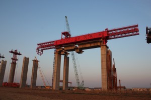
HZQ59/80 Segmental Assembly Bridge Girder Launcher Calculation Report
(1) CALCULATION CONDITION
1) Rated lifting capacity 80t
2) Span 58.58m
3) Lifting speed 3m/min
4) Dynamic load effect coefficient as lifting loads
5) In working condition wind speed 35m/s, wind pressure
In non-working condition wind speed 46.5m/s, wind pressure1.35×103N/m2
6) Stability coefficient as crossing piers n>1.5 (in special working condition wind speed limitation 4 grade, wind speed 8m/s, wind pressure 40 N/m2)
(2) DESIGN OVERVIEW
In installing girders working conditions, irrespective of structure dead load of gantry crane for carrying girders and take into consideration simple connection between gantry crane structure and bridge girder launcher rear part but the factor is not fixed. Under the crossing pier condition, structure of gantry crane for carrying girders is connected firmly with that of the bridge girder launcher, considering the influence the gantry crane structure on the bridge girder launcher structure.
Main girder stiffness and load coefficient is designed to meet users’ demand but does not follow China Standard.
In non-working condition with rare wind and snow, add a horizontal connection system on the main girder midspan to connect two main girders together if the bridge girder launcher has a large span.
(3) LOAD CALCULATION
3.1 Rated load:PQ=80 t
3.2 Structure dead weight load
Main girder and guide beam
PG1=148+23=171 t
(therein main girder for gantry crane for carrying girders 20.5t)
Front support leg PG2=3.4 t
Middle support leg PG3=27.7×2=55.4 t
Gantry crane support legs PG4=13 t
Trolley and sling PG5=40 t
Main girder dead load distribution rule (dead weight of per unit length)
Main girder (two sides) q= 2.08 t/m
3.3 Horizontal load inertial force
1) Launcher moving inertial force PHD (main girder, support legs, trolley, sling and lifting loads)
Launcher moving speed with full load 3m/min(0.05 m/s), if starting and brake time is considered 3s, accelerated speed a=0.017 m/s2
PHD=φ5ma =1.5 ma
Get : all parts PHD:
Main girder
PHD1 =1.5×148×1000×0.017=0.4 t;
Support legs
PHD2 =1.5×(3+48)×1000×0.017=0. 13t;
Trolley and sling (with overhead crane) PHD3=1.5×44×1000×0.017=0.11 t;
Lifting loads PHD4=1.5×80×1000×0.017=0.2 t;
Guide beam PHD5=1.5×23×1000×0.017=0.059t;
Load distribution type
Inertia force of main girder and guide beam is distributed as uniform load.
Main girder (single girder):
Guide beam (single guide beam):
Inertial load of trolley, sling, lifting loads and support leg is distributed as concentrated load :
2) Trolley moving inertial force PHX (trolley, sling and lifting loads)
Trolley moving speed with full load 4.6m/min (0.077m/s), if starting and brake time is considered 3s, accelerated speed a=0.026 m/s2
PHX=φ5ma=1.5 ma
So :PHX=1.5×(44+80)×1000×0.026=0.5t
3.4 Horizontal lateral force as trolley moves askew.
1)Lifting object is at midspan of trolley
So R1=75t L/B=6.5/3.5=1.86
After looking up the table λ1=0.05(L-span, B-support legs central distance)
Ps1=0.5∑R1•λ1=0.5×75×0.05= 1.875t
2)Lifting objects are nearest to the support leg
So R1=115t
Ps2=0.5∑R1•λ1=0.5×115×0.05=2.9t
Therein ∑R-sum of wheel pressure of trolley brake wheel at one side, λ-horizontal lateral force coefficient


