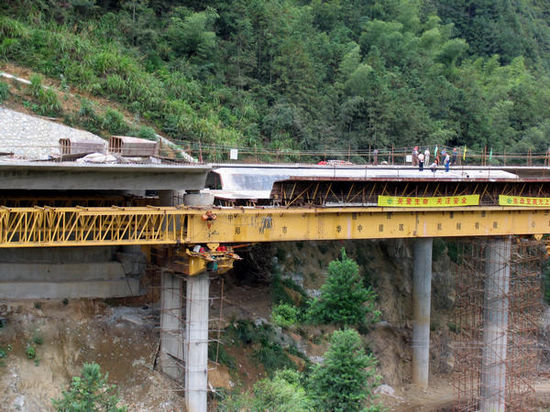
Downstroke Movable Support System

Pictrues
Application range and usehide/show
MSS downstroke movable support system bridge making machine is bridge construction equipment using methods of cast-in-situ and span by span construction, designed to meet continuous box girder construction.
The downstroke movable support system adopts support under the bridge deck, uses two groups of steel box girder to support pattern plate, and realizes the complete machine to move laterally and longitudinally to cross piers by main girder bringing with formwork and pattern plate. Equipped with 3 sets support legs, as starting pouring concrete beam, two sets legs as support, before crossing piers, the third set leg moves backward to be installed on pier at front of it, meeting the demand of crossing piers, span by span construction, moving backward repeatedly. The movable support system is equipped with 4 sets hydraulic systems to realize automatic jacking of formwork, lateral moving and longitudinal moving.
Main features and advantageshide/show
The machine is installed below the bridge floor, supporting the templates with two sets of steel box girder. The moving between the piers is carried through the transverse moving and longitudinal traveling of the main girder mould bases with the template. With three sets of support legs, two of them is used to supporting while casting the concrete girder. As the machine needs to move from one pier to next pier, the third support leg shifts to the front pier and fix on it in order to accomplish the task. The moving method of the machine is like this, one by one. Equip with four sets of hydraulic system, the machine can realize the jacking up, transverse and longitudinal traveling automatically.
Main Parametershide/show
The MSS650 is just a typical example.
| Item/ Data /Model | MSS650 |
|---|---|
| Span(m) | 30 |
| Girder-casting Weight(one time) (t) | 650 |
| Applicable Longitudinal/transverse Gradient | 0.2-2.5% |
| Longitudinal Speed (m/min) | 0.5 |
| Self Weight(t) | 300 |
| Max Anti-force At Working (m/min) | 316 |
| Max Anti-force At moving(t) | 103 |
The design basis of producthide/show
MSS600 Downstroke Bridge Creating Machine is designed according to the <《Crane Design Standard》 (GB/T3811)
《Steel Structure Design Standard》 (GB50017)
《Code for Design of Highway Bridges and Culverts》 (JTJ021)
《The General Safety Technical Requirements for Engineering Machinery》 (JB/T6030)
《Code for Construction and Acceptance of Electrical Appliance Installation Engineering》 (GB50256)
《The General Technical Conditions for Hydraulic System》 (GB 3766)
《Code for Construction and Acceptance of Steel Structure》 (GB50205)
《Mechanical Properties of Fasteners—Bolts, Screws and Studs》 (GB 3098.1)
Main requirements of designhide/show
■ When the machine counters the conditions like: the continuous girder or transferring, it is equipped with the functions of counterweight mechanism and overall opening and closing.
■ The traveling method is walking hydraulic push-put, the support leg rearrangement needs the auxiliary facility.
■ The machine is double main girder, supporting with the corbel and piers.
■ The max. anti-force of the supporting beam is 316N at working.
■ The construction speed : 12 days for two piers ( later it will be 11 days for two piers).
■ The max. anti-support force of support roll while traveling: 103N.
■ Applicable longitudinal slope/lateral slope: 2%/2%.
■ The deflection of main girder: 1/700
Main mechanical manufacturing technologyhide/show
quality control of manufacturing processhide/show
Tracing data and leaving factory data of producthide/show
The method and steps of installationhide/show
Checking methods after installation of producthide/show
operating requirements and attentionhide/show
Time and item of maintenancehide/show
Disassembly and steps of transferring sitehide/show


